Basic Knowledges of Step Voltage Regulator
Background
The voltage of 10KV distribution line in rural areas usually fluctuates greatly with the change of seasons and day and night. Especially in the rural drainage and irrigation period, voltage quality is difficult to guarantee. At present, there are two main voltage adjustment methods: One is to adjust the main transformer tap, the other one is to adjust the voltage by compensating for reactive power.
Adjusting the tap changer of the main transformer can not only change the voltage level, but also change the power distribution of the system. In this way, the tap of the main transformer is adjusted according to the load of the system to make the substation output voltage meet the predetermined requirements. Since the basis of regulation is based on the bus bar of the substation, it is about to limit the voltage level of the bus to a predetermined range in order to meet the voltage deviation requirements within a certain output radius based on the bus. However, the voltage requirement at the end of the long-distance power supply line cannot be satisfied, and the substation bus will have several outgoing lines, and the load curve of each outgoing line will be different, and the voltage drop will also be different, so the voltage of all lines cannot be guaranteed to meet the requirements. Therefore, this voltage regulation method has poor flexibility and pertinency. When the feeders are complex, the voltage near the substation is often high, while the voltage far from the substation is low. Moreover, at present, many main transformers of 35KV or 66KV small substations in rural areas do not have the capacity of on-load regulating voltage, so the investment in transforming them into on-load regulating voltage transformers is relatively large, which also limits the application of this voltage regulation way.
Using reactive compensation to improve the reactive power of the system can improve the voltage quality of the end user. Outdoor capacitor compensation is a voltage adjustment measure which is widely used in agricultural network system at present. It is small in size and easy to install. But most of the capacitors installed in rural distribution network need manual operation and cannot be switched automatically. Moreover, in some areas, when the off-peak load is running, the voltage is too high after the compensation capacitor is put in, which further increases the iron loss of the distribution transformer and thus increases the line loss. More importantly, capacitor compensation is mainly to improve the power factor of the line, voltage regulation effect is very limited, only relying on capacitor compensation can not solve the problem of voltage reduction caused by the line length, line diameter, resistance. In order to solve the quality problem of 10KV feeder voltage, we presents the design method of feeder step voltage regulator.
What is a Voltage Regulator?
•Voltage Regulator - A device which will provide a constant voltage output under varying input voltages and load currents
•By standards, regulates +10% voltage and
–10% voltage.
•Total of 33 steps; = 5/8% voltage per tap.
•16 steps in the Raise direction, 16 steps in the Lower direction, and one Neutral position.
Purpose of Feeder Step Voltage Regulator
Solving voltage drop problem

Working Principle
The voltage regulator is composed of a specially designed on-load voltage regulator and an auto-transformer. It can automatically "monitor" and smoothly adjust its output voltage to keep its output voltage within the required voltage range.
32 steps of voltage regulation: so that the amplitude of each step of voltage regulation is 0.625% of the line voltage, as shown below:

There are two types of line voltage regulators: single-phase and three-phase. Compared with the huge volume and high cost of three-phase voltage regulators, single-phase voltage regulators are compact, easy to install, and more flexible in application. At present, most voltage regulators in the world adopt single-phase structure, and Rockwill Power System also uses it as a standard design.
Three Basic Parts of a Voltage Regulator
•Auto transformer - A transformer in which part of one winding is common to both the primary and secondary winding
•Load Tap Changer - A switch designed to work under load to change the configuration of a transformer coil
•Voltage Regulator Control - A control which senses the system and automatically commands the tap changer.
Regulation Methods

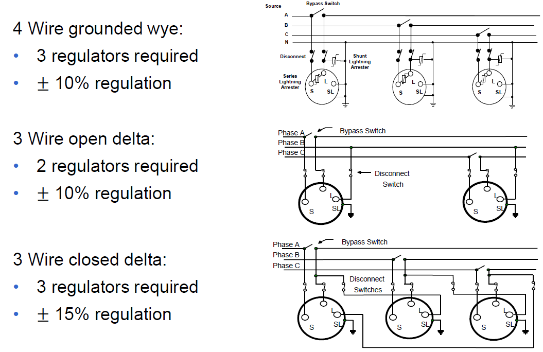
Connection Ways

Regulator Size Calculation
•For the regulator voltage rating:
Line voltage = phase voltage × √3
•For the regulator current rating:
Line current =Transformer size /(Line voltage × √3)
•For regulator kVA rating:
kVA rating = Phase voltage × Line current × %Regulation
Rockwill Step Voltage Regulator Lists: